Curved Poly
Intro
General Features
Shape Editing
First Steps into Shape Editor
User Interface and Settings
Operators and Views
Pointings Operator
Vertices
Handles
Edges
Polygons
Selection Operator
Tessellation Operator
Elasticity and Edge Normal
Curved Poly Inspector
Primitives and Demos
Assets and Libraries
Advanced Shape Editing
Hide Operator
Shape Control Operator
UV Operator
Backgrounds Operator
Creation and Composition
Anatomy of a Curved Poly Model
Create Operator
Geometries Operator
Unwraps Operator
Edit Operator - Overview
Edit Operator - Making Custom Primitives
Edit Operator - Inspecting and Fixing
Tessellation Operator

Fig. 1 Tessellation Operator
The Tessellation Operator is very similar to Selection Operator, but it's dedicated to Tessellation Hints. Tessellation Hints are little labels (all the characters from A to P, in alphabetical order) which describe how much segments should be used to tessellate an edge.
I suggest to change the Shading Mode of your active Scene View from Shaded to Wireframe or Shaded Wireframe to have a better visual feedback on the number of triangles.
Curved Polys tessellation is all about determining how much segments should be used to tessellate each curved edge. Then, the Filling Algorithm on each polygon will do the rest.
The exact number of segments is defined at Run-Time, after a specific Level of Detail as been assigned to the entire model; such Levels of Details are defined inside LoDs tables, which are stored in LoDs Assets. Usually, A means a very little amount of segments (the minimum being 1) and P means an impressive huge amount of segments. For practical purposes, I suggest to use only the hints from B to G, reserving the A hint for special situations in which you only need to have a Placeholder* , and all the Hints after G for rare situations or special uses.
*When the number of segments on each edge is less then 3, there is no practical reason to use Curved Poly, since the Curved Poly model will have more vertices than the final tessellated mesh.
Last but not least. On each edge there are two hints, one for each side. Curved Poly tessellates each edge in a smooth way, using an intermediate amount of segments, in order to have more segments near the smaller hint and more segments near the greater hint. An example of this is shown in the Curved Poly Inspector section.
Tessellation Operator Instruments
With the tessellation operator you can select any group of edges, but the operator ignore polygons or vertices. After selecting an edge, also its extremes vertices will be selected, but you don't have a way to directly select each single vertex (or each single polygon). As for the Selection Operator you have access to:
- a
 Circular Selector: a circle will be drawn and you will be able
to select edges by dragging it on the Scene View. You can also change the size of the circle with the buttons O and P on the keyboard.
Circular Selector: a circle will be drawn and you will be able
to select edges by dragging it on the Scene View. You can also change the size of the circle with the buttons O and P on the keyboard. - a
 Rectangular Selector: you can drag on the Scene View a rectangle
to change the area of selection.
Rectangular Selector: you can drag on the Scene View a rectangle
to change the area of selection. - the
 Part option: elements will be selected when the circle/rectangle
cover even a little part of them.
Part option: elements will be selected when the circle/rectangle
cover even a little part of them. - the
 Full option: elements will be selected only when the circle/rectangle
cover them entirely. The algorithm here takes into account only the visible part of edges, so it’s more correct to say that the edge is selected when its visible part is covered by the tool.
Full option: elements will be selected only when the circle/rectangle
cover them entirely. The algorithm here takes into account only the visible part of edges, so it’s more correct to say that the edge is selected when its visible part is covered by the tool.
After you have selected a group of edges, you can change their hints in two ways:
- In the scene view you will find a couple of little spheres on every selected edge. Each sphere has a little label showing the hint for one of the two sides of each edge. Moving the sphere from the center to its extreme vertex will change the hint, from A (near the center of the edge) to P (near the position of the vertex).
- In the Dynamic Menus Section you will find a panel named Edge Hints with 16 buttons, one for each possible hint. Clicking on a button will change the hints for all selected edges at once. The hints from B to G have a bolder font, this is to suggest you to use them the most. (Almost all the demo models are made with this practical choice, for instance).
LoDs Assets
Curved Poly tessellation algorithms are based on a Levels of Detail Matrix which can be customized. Such table is stored in the project with a specific asset called LoDs. You can find the default settings for the LoDs table at Assets/CurvedPoly/LoDs/LoDs. If you open the asset, it should look like this:
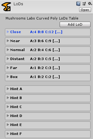
Fig. 2 A LoDs table
Each LoD is a record in the table and you can add how much LoDs you wish with the Add LoD button. On each LoD you will find a set of sixteen integers value from Hint A to Hint P. This is the way values for each hint are provided to the algorithms.
By default, you will find six clearly understandable LoDs named Close, Near, Normal, Distant, Far and Box. Their values have been set up to be coherent with our tessellation algorithms. That said, for practical situations you will probably choose to use the default settings and limit the use of LoDs only to some values, maybe Near-Normal-Far which is a fair enough choice.
If you wish to change LoDs records you can:
- Create your own custom LoDs asset in the Project Panel popup menu or with the Assets Menu selecting Create > Curved Poly > LoDs.
- Add new LoDs with the Add LoD button. Pressing more times the Add LoD will automatically create a set of incremental LoDs values which may be a good starting point.
- Clone a pre-existent LoD with the Clone Button inside the LoD record.
- Clone a pre-existent LoD with doubled values with the Clone(2x) button inside the LoD record.
- Remove any load you don’t wish to use with the Remove button.
- Rename the LoD the way you like. You should always use unique names to make it simple to distinguish them.
Below the records of the table you will also find the helpful hint views, which contain the same data organized by hint (the column of the table) and not by LoD (the row of the table).
When you have a LoDs Asset (either the default one or a custom one), you can assign it on your Curved Poly Behaviour.
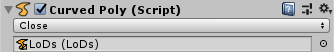
Fig. 3 LoDs assignment
The choice above the LoDs Asset will be automatically updated with the list of all available LoDs. Each time you change the LoD, your Mesh will be recalculated with the alternative Tessellation Values. This Mechanic is available both in edit mode and in play mode, since its part of Curved Poly Runtime.
LoDs Assets and Tessellation Hints at work
Each edge has two Tessellation Hints assigned, one for each side of the edge. In order to understand how they work, I will start from the simple case in which the two values on the edge are the same.
Let’s suppose that an edge as been assigned the Hint D on both sides and that the current Curved Poly is using the Default LoDs with the Close LoD active. While pointed in the Pointings Operator the edge should look like this:
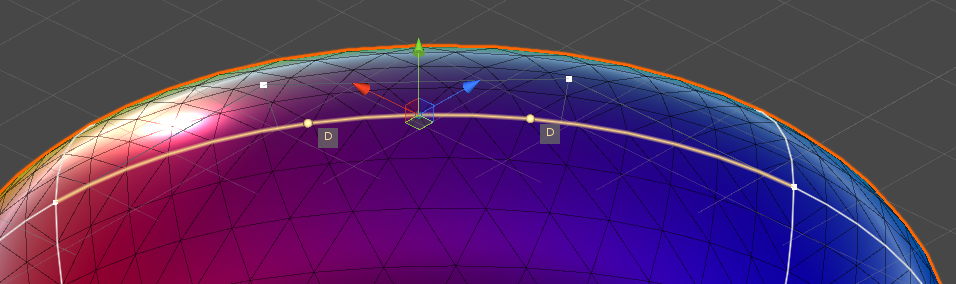
Fig. 4 Hint D + Hint D, Default Close LoD
Where I changed the Shading Mode of the Scene View to Shaded Wireframe to see the current wireframe. The value for Hint D in the Default Close LoD is 16. Indeed, the edge is tessellated uniformly with 16 segments. If you now get back to the inspector and change the LoD, you should always see that the number of segments is the same you wrote in the LoD record for the Hint D. For instance if you choose the Default Normal LoD, you will get 8 segments.
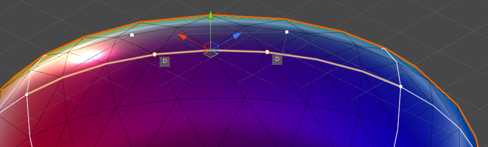
Fig. 5 Hint D + Hint D, Default Normal LoD
Let’s now change the Hints. Select the Default Close LoD in the Inspector to get back to 16 segments. Then change the Hints to Hint M to increase the tessellation. This time the edge will be tessellated with 52 segments, where 52 is the value you can find in the Default Close LoD for Hint M.
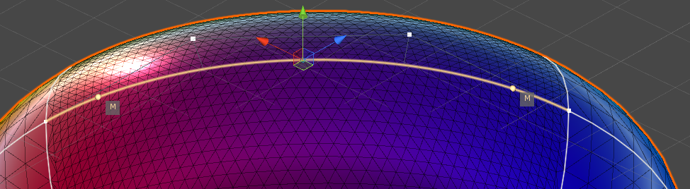
Fig. 6 Hint M + Hint M, Default Close LoD
You can easily see that the change affects both the edge and the two polygons attached to the edge. The changes in tessellation are local and will not affect the rest of the model.
Now let’s try the case with different LoDs on the same edge. We set Hint D on one side and Hint M on the other. In this way my algorithms will evaluate a smoothly distributed tessellation where the number of Segments is an intermediate value between the one of Hint D and the one of Hint M and the Segments are placed with a growing pace in order to be closer to the side where we put the higher Hint. You can easily watch how this work by slowly changing the hints on both sides.
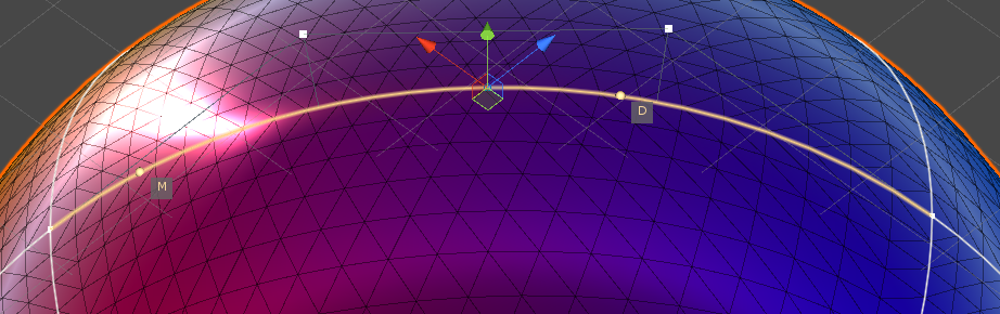
Fig. 7 Hint M + Hint D, Default Close LoD
<< Prev Next >>