Curved Poly
Intro
General Features
version 1.3 News
about the Shadow Framework
Setup
How to Start
Editor Interface
Editor Windows
Tools Sets
Assets
Assets Worflow
Game Objects
Assets Upgrade to 1.3
Common Tools
Selection
Hiding and Visibility
Parts List
Shape Tools
Selection Transform
Backgrounds
Handles and Edges
Polygons
Shaping Options
Tessellation
LoDs Assets
Hints (A to P)
Composition Tools
Primitives
Custom Parts
Compositing
Materials Tools
Unwraps Tools
UV Panel
Advanced Shape Tools
Shape Edit Tools
Shapes Customization
Cutting and Splitting
Making Shapes
Exploiting other Tools
Issues and Fixing
Curves and Surfaces
Free Paths
Parametric Curves
Generating Surfaces
Update Surfaces
Advanced Shaping Tools
This Tools Sets requires Curved Poly - Maker
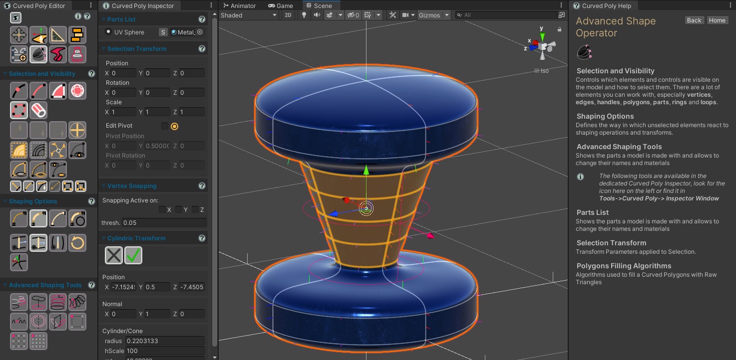
Fig. 1 Advanced Shape Tools
This ![]() Advanced
Shape Tools Set is an advanced version of Shape Tools, meaning that it has all
the same tools, plus a set of advanced instruments which will help you working on the shape of your models. There are 8 Advanced tools right now, the 8th having 3 alternatives setup, for a total of 10 buttons:
Advanced
Shape Tools Set is an advanced version of Shape Tools, meaning that it has all
the same tools, plus a set of advanced instruments which will help you working on the shape of your models. There are 8 Advanced tools right now, the 8th having 3 alternatives setup, for a total of 10 buttons:
 Circleify:
force all selected vertices to lay on a circle.
Circleify:
force all selected vertices to lay on a circle. Cylindric
Transform: a transform based on a cylindric volume built over a set of vertices.
Cylindric
Transform: a transform based on a cylindric volume built over a set of vertices. Curved
Tube Transform: a transform designed to help you model tubular objects, affecting both
selected and unselected vertices. It simplifies the way you shape groups of vertices at once.
Curved
Tube Transform: a transform designed to help you model tubular objects, affecting both
selected and unselected vertices. It simplifies the way you shape groups of vertices at once. Proportional
Transform: a transform affecting both selected and unselected vertices, unselected vertices
transform is weighted based on the distance they have from selected ones.
Proportional
Transform: a transform affecting both selected and unselected vertices, unselected vertices
transform is weighted based on the distance they have from selected ones. Sparkling
Transform: a transform which automatically replicates shaping actions to do on the handle
of a vertex to other vertices.
Sparkling
Transform: a transform which automatically replicates shaping actions to do on the handle
of a vertex to other vertices. Symmetry:
a transform which defines a set of symmetry relationships between vertices, allowing transforms among them.
Symmetry:
a transform which defines a set of symmetry relationships between vertices, allowing transforms among them.  Mirror:
a transform which Flips selected elements with respect to a mirroring plane.
Mirror:
a transform which Flips selected elements with respect to a mirroring plane.

 Free
Form Transform (FFT): a transform which makes you shape an object by moving vertices on
a control grid. You have three variants ( 1x1x1, with 8 total vertices, 2x2x2, with 27 total vertices, and 3x3x3 with 64 total vertices ).
Free
Form Transform (FFT): a transform which makes you shape an object by moving vertices on
a control grid. You have three variants ( 1x1x1, with 8 total vertices, 2x2x2, with 27 total vertices, and 3x3x3 with 64 total vertices ).
All these tools will need some selection to work. Once any operation has been activated, you will enter into an operation state which will block many other actions. In order to get out of the operation and select a new one you can:
 Apply: Confirm any change and exit the the operation.
 Close:
Remove any generated vertex or edge and exit the operation.
Close:
Remove any generated vertex or edge and exit the operation.- Press Enter: like Apply.
- Press Esc: like Close.
- Change Operator (entering another one from the menu on the left of the scene view): like Apply.
So, if you change operator while one of the building operations is active, the operation will be automatically applied.
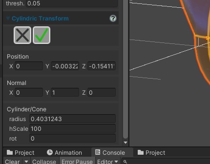
Fig. 2 Each advanced Shape Tools open a new Section in the Dedicated Inspector. Here you can access more controls, change its paratameters, or Close it for instance.
 Circleify
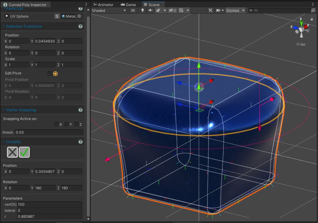
Fig. 3 Circleify active on one of the Edges Loop of a Curved Cube
Circleify forces a set of vertices to lay on a circle and than gives you control on the circle parameters. This is very useful if you have a closed path of edges and you want to make it a perfect circle. It is also useful if you have a circle in you model or primitive and you want to shape it without breaking its circular shape. Here the parameters you can change:
- Position: the Position of the center of the circle
- Rotation: absolute Rotation with respect to a Default circle laying on the XZ plane. This should help you correct the circle orientation when needed.
- Vertical(%): scaling factor applied on the handles of the vertices of the circle. This scaling is applied only on the Vertical direction, that is the direction being at 90 degrees (orthogonal) to the circle plane.
- rotation: lateral inclination of the handles of each vertex. This is applied with rotational symmetry (so if two vertices are in opposite direction, this rotation will happen towards opposite directions.)
- r (radius): radius of the circle.
The rotation, Vertical and r can be controlled with magenta arrows in the scene view. Position and rotation can instead be controlled with Unity transform tools. All the parameters can be changed in the menu.
 Cylindric Transform
Fig. 4 Cylindric Transform active on a selection of Rings of a Curved Cylinder
Cylindric Transform is similar to Circleify, but it does not force vertices to take some specific shape. It rather generates a cylindric shaped volumes around selected vertices, and then makes you transform the cylindric volume to reshape all that vertices at once. This is a very useful instrument if you want to create rotational surfaces from cylindric primitives for instance. Here the parameters you can change:
- Position: the Position of the center of the cylindric volume.
- Normal: The vertical direction of the cylindric volume, which is by default (0,1,0) since this is coherent with the setup of many primitives you can generate with Create Operator. This parameter can only be changed in the menu with a manual insertion of values.
- radius: radius of the cylinder.
- hScale(%): vertical scale of the cylinder, in the direction of the normal.
- rotation: lateral inclination. This is applied with rotational symmetry, and allows you to transform the cylindric volume into a Conic one.
The rotation, hScale and rotation can be controlled with magenta arrows in the scene view. The Position can instead be controlled with Unity transform tools. All the parameters can be changed in the menu.
 Curved
Tube Transform
Curved
Tube Transform
Fig. 5 Curved Tube Transform used to shape a Bar Primitive into something more complex.
Curved Selection Transform allows you to transform groups of points at once in a way that makes transforms on edges between the groups blend smoothly. Before you enter the transform you need to plan carefully which vertices you want to select:
- Selected vertices will become lead vertices: lead vertices controls the position of other vertices.
- Unselected vertices will become passive vertices: each passive vertex is assigned to one of the lead vertices, depending upon their distances. (There is no other options about this, but we may have more options in the future)
Once active,the operation works in a way which is similar to the pointings operator, but you will be allowed to point only lead vertices. Once you point a lead vertex, all its assigned passive vertices will be selected and also the edges connecting vertices in the group will be selected. The entire group will follow any transform you apply to the lead vertex.
On each lead vertex you can also find 6 transform handles which will allow you to scale or screw the group on its relative x, y or z axis. The handles are 6 because there are separated scaling factor for down and up, left and right, forward and backward.
This transform always affect all vertices of your model with the exception of the ones which have been hidden, so you may want to hide parts of the model you don't want to be affected by these transforms. That said, it is recommended to use this transform on fresh Curved Polys with only one shape inside: after shaping it and saving the shape, you can always insert it into a more complex Curved Poly with the Insert button you can find in Create Operator
 Proportional
Transform
Proportional
Transform
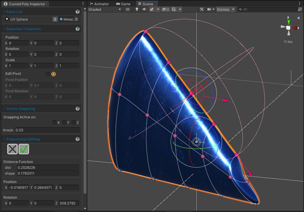
Fig. 6 Proportional Transform used to shape a Bar Primitive into something more complex.
Proportional Transform allows you to transform groups of vertices and make other unselected vertices follow the transform in a smooth, weighted way. Before you enter the transform you need to plan carefully which vertices you want to select:
- Selected vertices will become full transform vertices: full transform vertices will follow the transform with a 100% weight. Usually it may make sense to activate the tool with only one selected vertex.
- Vertices within a specific distance from the selection will become passive vertices: each passive vertex is assigned a weight which depends on the distance.
- Vertices at a greater distance will be unaffected
Once active, it will be possible to transform the selection using Unity Transform Tools, like it happens in the Selection Operator. Full transform vertices will follow the transform, while passive vertices will change their position more slowly, at a pace which depends upon their weight. During the transform every vertex will be drawn has a sphere with a color which blends between gray and magenta: gray means that the vertex has a 0% weight assigned and magenta means that the vertex as a 100% weight assigned. A Distance function is applied to determine such weights with this parameters:
- Dist (Distance Function): the distance at which the weights become 0%.
- Shape (Distance Function): a parameter in the [0,1] range which determines how rapidly the weights will drop to 0%.
You can control both parameters in the menu or through a pair of magenta arrows in the scene view
 Sparkling Transform
Fig. 7 Sparkling Transform used to shape a Bar Primitive into something more complex.
With Sparkling Transform you can replicate changes you make on a vertex handles to other vertices. You need to select the vertices you want to work on, than the transform will try to match the handles across that vertices in order to apply symmetric changes. There are two relevant cases in which this transform does a good work:
- You select a set of vertices having all the same editing normal and the same amount of handles (this is common if you are working on a Curved Poly primitive).
- You select a set of vertices on a circle. Any change will (hopefully) be applied in a way which is symmetric to the center of the circle.
The transform will work in any case, but it may fail matching handles on different vertices if it doesn't find a good mapping of the handles.
Once active, you can point on a vertex and then you can point on one of its handle to change its length, roll or pitch, the same way you can do in Pointings Operator, but here any change is replicated to all mapped handles on the other vertices, making all selected vertices change in shape at once in the most symmetric way possible (again: this depends on how good is your starting selection so you should have a try and maybe Close the operator to roll it back and make a different selection of vertices)
Mirror
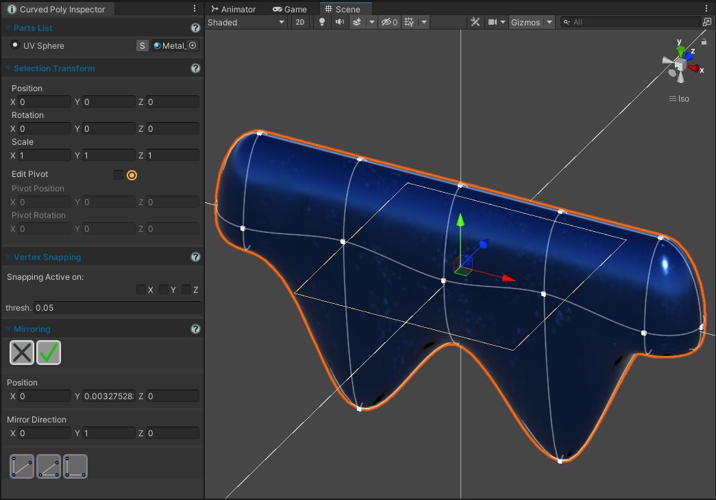
Fig. 8 Mirror applied (to reflect the Shape modeled in the symmetry section).
Mirroring flips a set of elements mirroring them with respect to a mirroring plane.
How to Use: select any group of polygons. Click on the button to flip it on x direction. Use the controls here to change how your selection is flipped.Position: Position of the mirroring plane.
Mirror Direction: Mirroring Direction, which is the orthogonal/perpendicular direction the Mirroring plane is facing.
![]() Mirror
Direction XY: change the mirror direction to be forward (0,0,1)
Mirror
Direction XY: change the mirror direction to be forward (0,0,1)
![]() Mirror
Direction YZ: change the mirror direction to be right (1,0,0)
Mirror
Direction YZ: change the mirror direction to be right (1,0,0)
![]() Mirror
Direction XZ: change the mirror direction to be up (0,1,0)
Mirror
Direction XZ: change the mirror direction to be up (0,1,0)
 Apply: Close the Mirroring Editor and apply changes.
![]() Close:
Close the Mirroring Editor undoing all the changes.
Close:
Close the Mirroring Editor undoing all the changes.
Symmetry
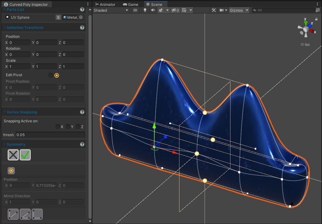
Fig. 9 Symmetry used to shape a Bar Primitive into something more complex.
Symmetry defines a set of symmetry relationship between vertices. This relationships are built using a Mirroring Plane working as the one used in Mirroring. Vertices being ON the plane, are marked with a big yellow spheres. Vertices having a symmetric pair vertex across the mirroring plane are connected to their counterpart with a straight line in the mirroring direction. Moving one of the vertices in the couple, will move the other one as well.
How to Use: select any group of polygons. Click on the button to generate a set of symmetric relationship. If you move a vertex with a symmetric relationship, also the vertex with which it is in relationship will be moved.![]() Mode:
activate/deactivate the editing of the Mirroring Plane. When active, you can change the mirroring plane and vertices relationship are recomputed. When not active, you can't change the mirroing plane, but you can move the vertices around it.
Mode:
activate/deactivate the editing of the Mirroring Plane. When active, you can change the mirroring plane and vertices relationship are recomputed. When not active, you can't change the mirroing plane, but you can move the vertices around it.
Position: Position of the mirroring plane.
Mirror Direction: Mirroring Direction, which is the orthogonal/perpendicular direction the Mirroring plane is facing.
![]() Mirror
Direction XY: change the mirror direction to be forward (0,0,1)
Mirror
Direction XY: change the mirror direction to be forward (0,0,1)
![]() Mirror
Direction YZ: change the mirror direction to be right (1,0,0)
Mirror
Direction YZ: change the mirror direction to be right (1,0,0)
![]() Mirror
Direction XZ: change the mirror direction to be up (0,1,0)
Mirror
Direction XZ: change the mirror direction to be up (0,1,0)
![]() Apply: Close the Symmetry Editor and apply changes.
Apply: Close the Symmetry Editor and apply changes.
![]() Close:
Close the Symmetry Editor undoing all the changes.
Close:
Close the Symmetry Editor undoing all the changes.


 Free Form Transforms
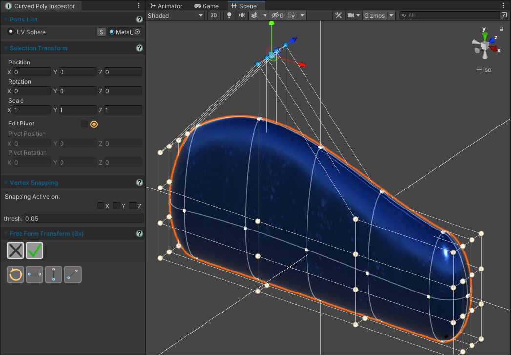
Fig. 10 Free Form Transform used to shape a Bar Primitive into something more complex.
The Free Form Transform generates a grid of vertices around your selection, so that you can reshape the selection by moving the points in the grid. The grid will be rendered as a set of lines connecting grid points which can be white or blue. You can make white grid points become blue by clicking them. You can then use Unity Transform Tool to translate, rotate or scale the subset of the blue points, while white points will keep unchanged. In the Menu you will find other useful buttons:
 Reset:
clear the set of blue vertices, making all of them white
Reset:
clear the set of blue vertices, making all of them white Extend on Grid (x): extend the set of blue vertices on x direction
 Extend on Grid (y): extend the set of blue vertices on y direction
 Extend on Grid (z): extend the set of blue vertices on z direction
Once inside one of the 3 available transforms, you can't change the grid size, but you can always Close or Apply the transform and open another one.
<< Prev Next >>