Curved Poly
Intro
General Features
version 1.3 News
about the Shadow Framework
Setup
How to Start
Editor Interface
Editor Windows
Tools Sets
Assets
Assets Worflow
Game Objects
Assets Upgrade to 1.3
Common Tools
Selection
Hiding and Visibility
Parts List
Shape Tools
Selection Transform
Backgrounds
Handles and Edges
Polygons
Shaping Options
Tessellation
LoDs Assets
Hints (A to P)
Composition Tools
Primitives
Custom Parts
Compositing
Materials Tools
Unwraps Tools
UV Panel
Advanced Shape Tools
Shape Edit Tools
Shapes Customization
Cutting and Splitting
Making Shapes
Exploiting other Tools
Issues and Fixing
Curves and Surfaces
Free Paths
Parametric Curves
Generating Surfaces
Update Surfaces
Making Shapes
Warning! This section contains some informations and/or images which were produced in version 1.2 docs. Therefore, this page shall be considered as a draft, the intended version 1.3 page will be ready soon.
This is where to start if you want to make a model from scratch.You will find more informations about this in the section dedicated to Custom Primitives
 Put Edges: activate the Put Edges Operation which allows you to
draw Curved Edges.This is one of the most important tools in Edit Tools.
Put Edges: activate the Put Edges Operation which allows you to
draw Curved Edges.This is one of the most important tools in Edit Tools.  Put Lines: activate the Put Lines Operation which allows you to
draw Linear Edges.
Put Lines: activate the Put Lines Operation which allows you to
draw Linear Edges. Put Vertex: activate the Put Vertex Operation which allows you
to add separated vertices.
Put Vertex: activate the Put Vertex Operation which allows you
to add separated vertices. Make a Circle: activate the Make a Circle Operation which allows
you generate a circle connecting two selected vertices. Availability: you need to have
2 (and only 2) selected vertices
Make a Circle: activate the Make a Circle Operation which allows
you generate a circle connecting two selected vertices. Availability: you need to have
2 (and only 2) selected vertices Make Polygons: automatically generate polygons. It only generates
polygons attached to any of your selected vertices. Possible candidates for polygons generation are found by Curved Poly starting from the Corners on the selected vertices: if somethings goes wrong, you may have some corners or bindings to fix . This
is one of the most important tools in Edit Tools. Availability: you need to have at
least one selected vertex
Make Polygons: automatically generate polygons. It only generates
polygons attached to any of your selected vertices. Possible candidates for polygons generation are found by Curved Poly starting from the Corners on the selected vertices: if somethings goes wrong, you may have some corners or bindings to fix . This
is one of the most important tools in Edit Tools. Availability: you need to have at
least one selected vertex Duplicate: activate the Duplicate Operation which allows you duplicate
your selection. The duplicated elements can then be moved around before you confirm the operation. This
is one of the most important tools in Edit Tools.Availability: you need to have at
least one selected vertex.
Duplicate: activate the Duplicate Operation which allows you duplicate
your selection. The duplicated elements can then be moved around before you confirm the operation. This
is one of the most important tools in Edit Tools.Availability: you need to have at
least one selected vertex. Flip Polygons: flip all selected polygons. Availability: you
need to have at least one selected polygon.
Flip Polygons: flip all selected polygons. Availability: you
need to have at least one selected polygon. Create Hole Joints: create a set of polygons which fills an hole.
The hole should be setup to be made of a closed set of aligned handles, otherwise the hole will only be filled partially. You only need to select one of the edges in the hole to activate this, but you may use Grow
Through Alignments to check if the hole is made of a closed set of aligned handles first.
Availability: you need to have at least one selected edge
Create Hole Joints: create a set of polygons which fills an hole.
The hole should be setup to be made of a closed set of aligned handles, otherwise the hole will only be filled partially. You only need to select one of the edges in the hole to activate this, but you may use Grow
Through Alignments to check if the hole is made of a closed set of aligned handles first.
Availability: you need to have at least one selected edge Create Bridge Joints: create a set of polygons which connects
two separated holes. The holes should be setup to be made of a closed set of aligned handles, otherwise the holes will only be connected partially. You only have to select one of the edges of each the two holes to activate this. Availability:
you need to have exactly 2 (and only two) selected edges.
Create Bridge Joints: create a set of polygons which connects
two separated holes. The holes should be setup to be made of a closed set of aligned handles, otherwise the holes will only be connected partially. You only have to select one of the edges of each the two holes to activate this. Availability:
you need to have exactly 2 (and only two) selected edges. Extrude Path: create a set of polygons which extrude a path of
aligned edges. Any selected edge will be automatically extended through its alignments. Only edges having no more than one polygons attached can be extruded. Availability:
you need to have at least one selected edge.
Extrude Path: create a set of polygons which extrude a path of
aligned edges. Any selected edge will be automatically extended through its alignments. Only edges having no more than one polygons attached can be extruded. Availability:
you need to have at least one selected edge.
Making Custom Primitives
Apart from the shapes you can generate with the Composition Tools, you can use the Edit Tools to generate new primitives or parts for you models in many ways. There are many approaches you can follow here:
- (A)Generate Edges and Make Polygons: you can create a model from scratch by modeling Edges (or Lines or Vertices) in the scene view. With two selected vertices you can also generate Circles. Once a you have a good set of edges and vertices you can fill it with polygons with the Make Polygons button which will guess the best polygons to fill your net of edges. Make Polygons take into accounts all the constraints required to make interpolation processes work well, so that the final mesh extracted from the polygons looks good.
- (B)Modify a Shape with Cuts and Extensions: you can start from a primitive or model you already have and delete parts you don't need with Canceling Buttons. With one vertex selected, you can also create a hole; when you have an hole (either generated after removing contents or with the Hole Operation) you can exploit the Extrude Path or the Hole Joints operations to add polygons to your shape.
- (C)Add Control Vertices: the best tool to add vertices (and edges and polygons) to a shape you already have is the Subdivide Edge Operation. This operation works on one edge at a time and allows you to split it into two halves. You may then extend it to adjacent polygons and to more edges in the case the polygons are quads. If you need something more specific which can't be accomplished with that operation, you can also rework parts of you shape by removing polygons or edges and using Put Edges + Make Polygons to generate different parts and details.
- (D)Combining and Stitching Shapes together: you can take two (or more) shapes of your choice and put them together in the same model. You can do this by using the Composition Tools, or you can also duplicate parts in the Edit Tools. Then, if they have an open part (eventually one generated with cutting tools), you can try to stitch/weld them together. You have more alternative ways to do so. One approach is to use Remove Doubles which also weld edges when their shape is approximative the same. Another solution is to take select two open also facing each other and go for Bridge Joints. You can also use Put Edges and Make Polygons to manually build a custom Joint between two holes in two separated surfaces.
- (E)Import a LOW POLY Mesh and Use Fixing Tools to Transform it into a Curved Poly: be sure to have the time to understand all the passages and the use of fixing tools. The mesh must be have a very low amount of faces, since each face will be transformed into a Curved Poly Polygon.
Here we will show a few examples of all this approaches. You can also look for Curved Poly tutorials online to learn more. Here an index of the examples:
- (A.1)Put Edges and Make Polygons
- (A.2)Manually create curved tubular surfaces with Make a Circle
- (A.3)Put Lines and Make Polygons
- (B.1)Cutting Parts of a Shape
- (B.2)Hole Operation
- (B.3)Extrude Path and Hole Joints
- (C.1)Subdivide Edge Operation
- (C.2)Manually Subdivide Edges or Polygons
- (D.1)Duplicate a Part and Weld the two clones together with Remove Doubles
- (D.2)Connecting two separated Parts with a Bridge Joint
- (D.3)Manually Connect two Parts with Put Edges and Make Polygons
- (E)Import LOW POLY Meshes to transform into Curved Polys
(A.1)Put Edges and Make Polygons
In this section we will discover more about Put Edges and Make
Polygons
With put Edges you can add vertices and Edges directly on the scene view. Before you start you should watch you Pivot Position: you will find the Pivot in the Scene View rendered as a yellow spheres surrounded by two circles, representing something which should look like a target. You can click on the target and use the Moving Tool to position it. When you add vertices with Put Edges a vertex position will be computed taking into account the mouse position and the depth of the pivot from the scene view camera perspective. So, for instance, if you place the pivot in (0,0,-1.5) and you choose to align the scene view Camera to X-Y axis (that is with the back and front view), every vertex generated with Put Edges will have a z coordinate equal to -1.5, and x and y coordinates computed from mouse position.
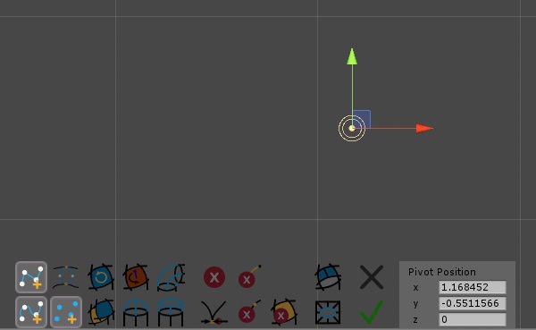
Fig. 1 Placing the Pivot
Entering and Exiting Put Edges Operation
Once you click on Put Edges you
will enter in an operation state from which you can exit in either one of these ways:
 Apply: Confirm any change and exit the the operation.
 Close:
Remove any generated vertex and exit the operation.
Close:
Remove any generated vertex and exit the operation.- Press Enter: like Apply.
- Press Esc: like Close.
- Change Operation (entering another one from the menu on the left of the scene view): like Apply.
Generating a Net of Edges
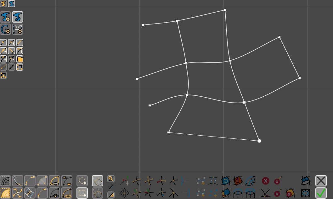
Fig. 2 Put Edges at work: Here we generated a complex net of Edges using Put Edges
Once Put Edges has been activated you will be able to add vertices
by clicking on the scene view. An edge will be generated between two consecutive edges, generating a continuous piecewise curve. You can break the sequence and start a new one by pressing Space,
or you can also Apply and re-enter pressing Put Edges again.
If you position your mouse on any existent vertex , its look will change: in this case Put Edges will re-use that vertex instead of generating a new one: you can exploit this to connect each vertex with more than two edges, so that you can create a complete net of edges. When a vertex is smooth and it has already more edges attached, new edges may be reshaped to conform (automatically) smoothness conditions for that vertex.
Making Polygons
Once you have a net of Edges you can start generating polygons.
To do so you first need to select at least a vertex: Curved Poly will generate polygons by looking for any closed loop of edges nearby your selected vertices. Then: you only have to press Make
Polygons and everything is automatic. A faster approach is to press Select All,
and then Make Polygons, in this way any possible polygon available in the model will
be generated. You can always cut unrequired polygons at a second time with  Cancel
Polygons. You may also Flip Polygons if they are facing the wrong side.
Cancel
Polygons. You may also Flip Polygons if they are facing the wrong side.
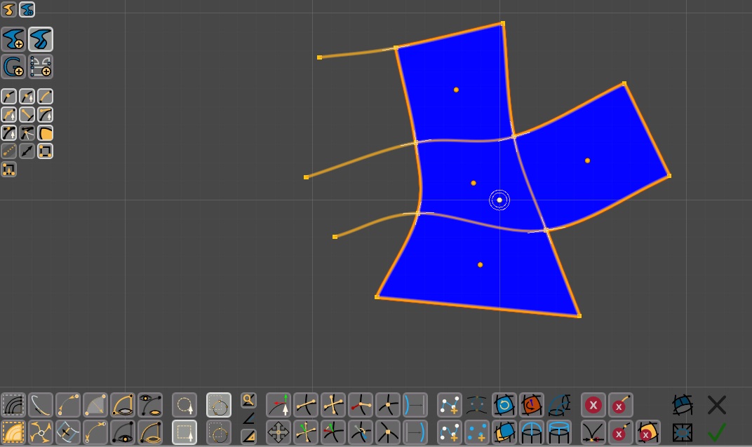
Fig. 3 Making Polygons
You may need to practice a bit with this before being able to use correctly Make Polygons. There are situations in which polygons can't be generated because there are edges with a bad shape, or with overlapping handles, which are blocked by Curved Poly to avoid issues with interpolation algorithms. When you think you did good but your polygons couldn't be generated, you can try go through an inspecting and fixing process. This is explained more in deep in a Dedicated Chapter
(A.2)Manually create curved tubular surfaces with Make a Circle
In this section you will discover how to use and exploit Make a Circle while working with Put
Edges and Make Polygons
Setup
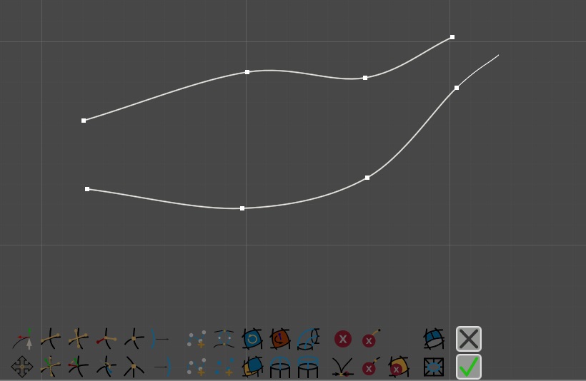
Fig. 4 Setup for Make a Circle
Let's start drawing two set of edges with Put Edges. Then we get out from put edges and we select two vertices, one for each vertex.
Make a Circle
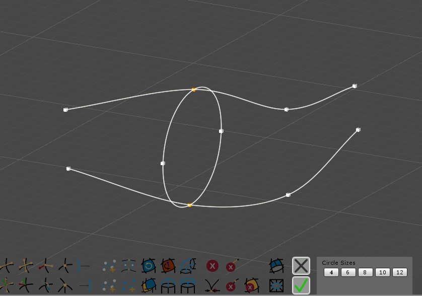
Fig. 5 Make a Circle
With Two selected Vertices you can enter Make a Circle.
By pressing the button you will enter into an operation state. Here you can:
- Choose the amount of edges used to make the circle in the Panel named Circles Sizes.
- Apply: Confirm any change and exit the the operation.
- Close:
Remove any generated vertex or edge and exit the operation.
- Press Enter: like Apply.
- Press Esc: like Close.
- Change Operation (entering another one from the menu on the left of the scene view): like Apply.
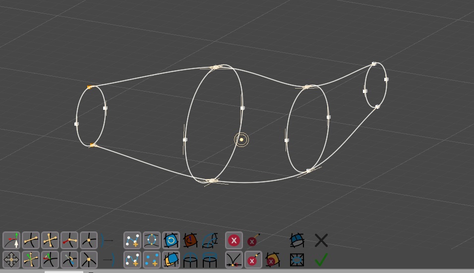
Fig. 6 Making more Circles
You can then use the operation more and more times, but you will need to exit and enter each time if you want to generate more circles.
Put more Edges and Make Polygons
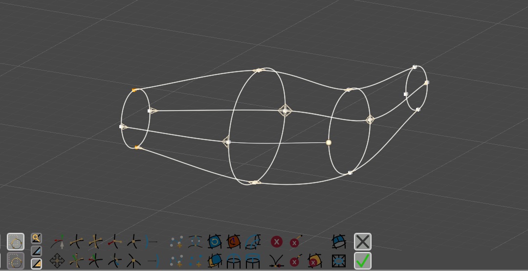
Fig. 7 Connecting Circles with Edges
You can add more edges to connect the addictional vertices generated with Make a Circle.
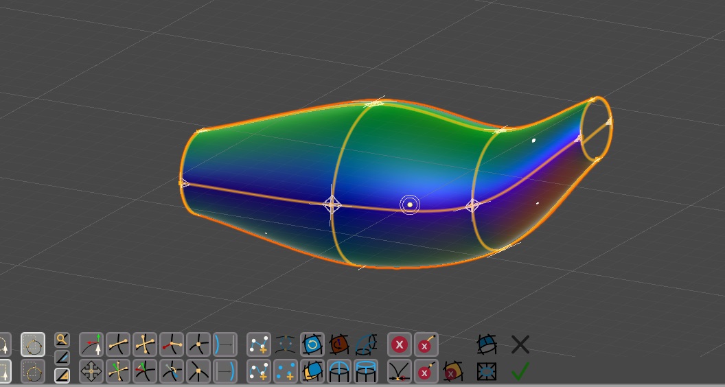
Fig. 8 Making Polygons
Now we Select All and make polygons. If there aren't issues
with the edges handles, you should see a custom tubular surface following the two curves you have drawn from the beginning. Know that you may need to use Flip
Polygons.
(A.3)Put Lines and Make Polygons
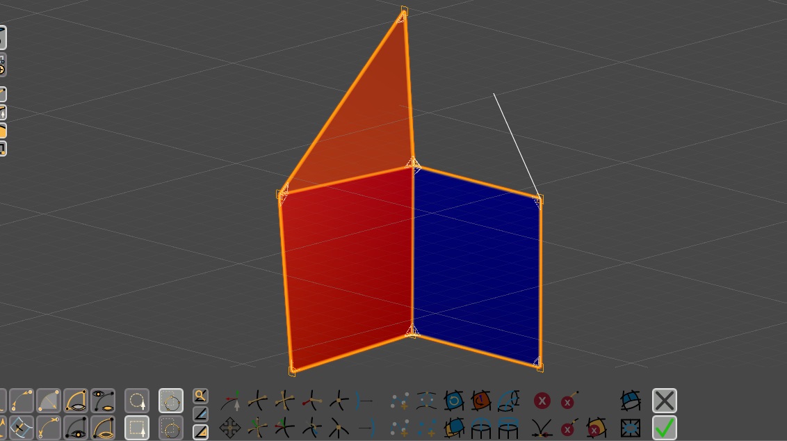
Fig. 9 Put Lines and Make Polygons
Put Lines works exactly like Put Edges, with a few important
differences:
- Lines are generated: instead of a continuous smooth curves, you will be able to generate a polyline with no alignments. Press Space to break the chain of vertices and generate a new polyline.
- Generated Vertices are Sharp by default instead of being smooth.
- If you reuse a smooth vertex it will become sharp.
Here each vertex is forced to be sharp, but you can change this at a second time.
Put Edges and Put Lines both work in ideal situations where everything is smooth if you Put Edges and everything is sharp if you Put Lines. That said, you can mix things up, making models which have linear parts and smooth parts. You can also have Curved Edges with Sharp Vertices and Linear Edges with Smooth Vertices. Mixing things this way is possible, but it requires a greater comprehension of a few mechanisms which will be discussed in the Inspecting and Fixing.
(B.1)Cutting Parts of a Shape
Cutting parts of a Shape is pretty straightforward. You need first to select the parts you want to remove, then you can:
 Remove Doubles (and Weld Edges): merge elements which are closer
than a specific distance that you can control. Availability: you need to have something
selected.
Remove Doubles (and Weld Edges): merge elements which are closer
than a specific distance that you can control. Availability: you need to have something
selected. Cancel: cancel any selected element.
 Cancel Vertices: cancel any selected vertex.
 Cancel Edges: cancel any selected edge.
- Cancel Polygons: cancel any selected polygon.
About Remove Doubles
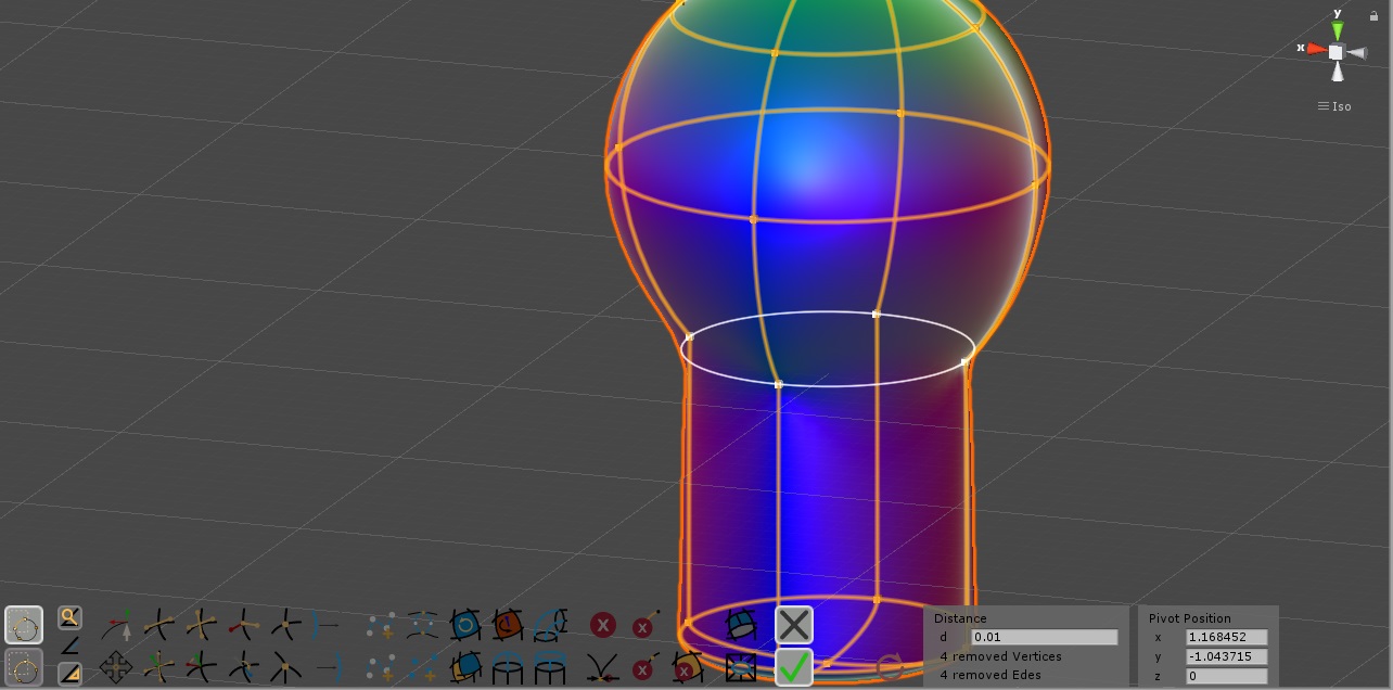
Fig. 10 Remove Doubles At Work, Stitching a Cut of a Sphere with a Cut of a Cylinder.
The Remove Doubles will put you in an operation state like similar
operations we have seen around, and you will need either to Close or Apply it
to exit.
While you use Remove Doubles you can setup the distance
d more and more times to fix your model. Every time you do this, you need also to press
on the  Update button to make Remove Doubles recompute the cut
with the new distance. The total amount of removed Vertices and Edges will be shown in the same panel below the distance d.
Update button to make Remove Doubles recompute the cut
with the new distance. The total amount of removed Vertices and Edges will be shown in the same panel below the distance d.
(B.2)Hole Operation
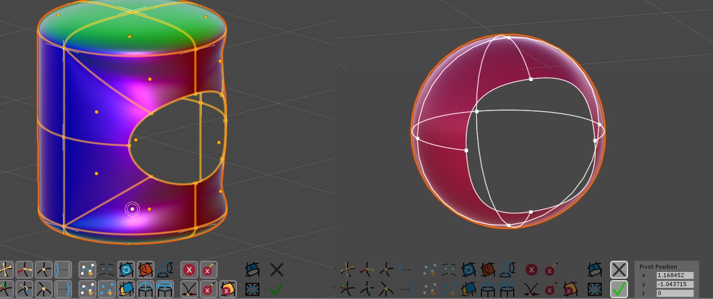
Fig. 11 Two Holes cut on two different primitives.
NOTE: as Version 1.0 Hole Operation still needs some works.
It works most of the times, but often generated polygons need some fixes afterwards. Since issues happen mainly on polygons, a general solution is to call  Make Polygons soon afterwards with the same selection. Or, since
often the problem is that polygons are flipped, you can try to correct them with a Flip Polygons.
Another important tip is to avoid pre-unwrapped models on this at all (unwrapping brings an additional degree of complexity in parts and you should avoid complex editing operation on parts splitted into Unwrap Groups).
Make Polygons soon afterwards with the same selection. Or, since
often the problem is that polygons are flipped, you can try to correct them with a Flip Polygons.
Another important tip is to avoid pre-unwrapped models on this at all (unwrapping brings an additional degree of complexity in parts and you should avoid complex editing operation on parts splitted into Unwrap Groups).
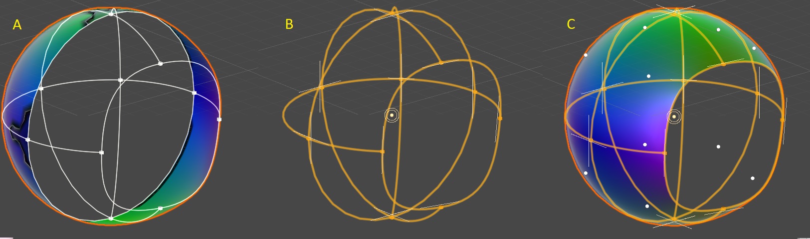
Fig. 12 Hole Operation Gone Wrong and fixed: (A) Bad Result (B) Cancel Polygons is used to remove all polygons (C) Make polygons is used to regenerate the polygons.
(B.3)Extrude Path and Hole Joints
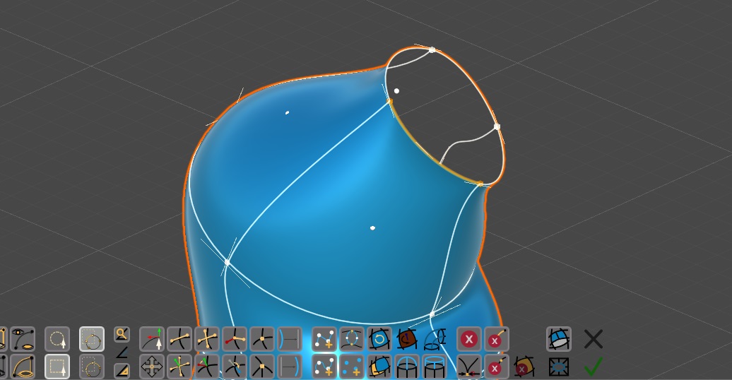
Fig. 13 Extrude Path and Hole Joints Correct Setup
When you have an open surface you can use Extrude Paths or Hole
Joints to add more polygons. This two actions (together with Bridge Joints which
is discussed in point (D.2)) are a preview of a paths systems which we are going
to introduce in one of the next versions of Curved Poly Maker. At the moment, they do their job well only if you make a good setup first: technically speaking, you need to have a closed set of edges, each one with a polygon on one side and free on the other side, and it may be better if you have put alignments first on that edges through the border. Basically, it has to be a closed border for an open surface. All the edges must be curves (lines may work, but it's not guaranteed), all the vertices must be smooth (sharp vertices may work, but it's not guaranteed). For example, this is the case if you start with a Cylinder Border primitive, or if you have generated a tubular surface exploiting Make
a Circle as explained in (A.2). If this is your case, you need to select one of
the edges of the border before activating either Extrude Path or Hole Joints (but you can select all the edges on the border if you like, or even some of them): since the edges are aligned, the software will automatically grow the selection through the border. Know that this two operations may still try to do something in any case once you have at least an edge selected: if you don't like the result you can always Undo it.
Extrude Path
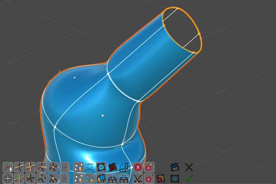
Fig. 14 Extrude Path
Extrude Path add a set of new polygons, one for each edge, which extrudes the open border.
Hole Joints
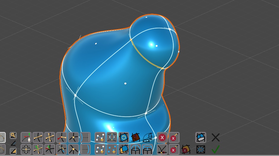
Fig. 15 Hole Joints
Hole Joints try to close the hole with a cap. To do so, it will try to guess a good position for a new vertex which will be added to the model, and will connect that vertex with the border by adding a new set of edges and polygons.
(C.1)Subdivide Edge Operation
Subdivide Edge allows you to split edges and polygons to add more details, increasing the amount of control vertices.
Polygons Sides With more Edges
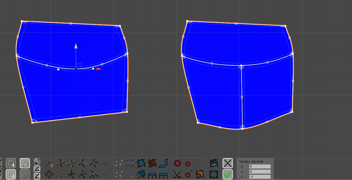
Fig. 16 On the left, 2 polygons having a side with 2 edges: one more control vertex appears in the center. On the right: a T-Junction between 3 polygons sharing 2 edges.
The side of a polygon can have more than one edge. Furthermore, a Group of edges can be used as one unique side for a polygon, and as separated sides for other polygons, making the polygons form a T-Junction. While planning your model, keep in mind that (apart from technical issues derived by the use of each operation) the only constraint here is that each edge can belong to a maximum of two sides of two different polygons, one on its left and one on its right, where left and right are computed based on the direction of the editing normals of the two extreme vertices of the edge.
Subdivide Edge Operation
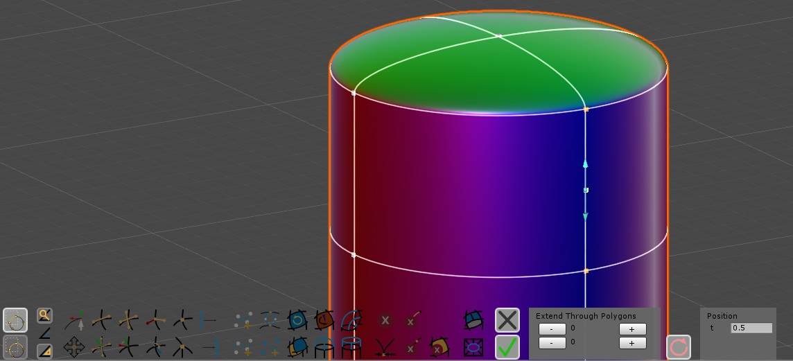
Fig. 17 Subdivide Edge Operation At Work 1 (Here the operation doesn't extend through polygons)
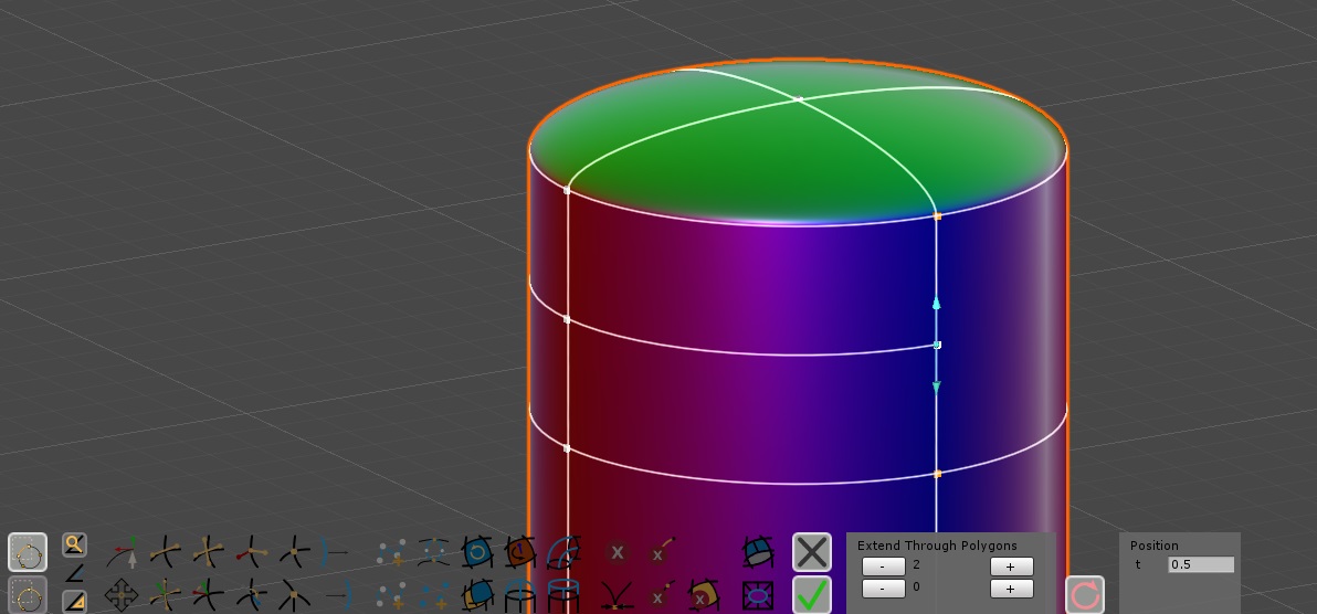
Fig. 18 Subdivide Edge Operation At Work 2 (Here the operation extends through polygons)
The  Subdivide Edge Operation will put you in an operation state like
similar operations we have seen around, and you will need either to Close or Apply it to exit.
Subdivide Edge Operation will put you in an operation state like
similar operations we have seen around, and you will need either to Close or Apply it to exit.
You need to select one (and only one) edge before entering the operation. That edge will be automatically split into two halves. After that you will be able to:
- Control the cut position: by either dragging the arrows on the scene view or changing
the t parameter in the Position panel in the menu. Changing this parameter will
not directly change the cut on the model, you will have to do an Update once
you have assigned a position you like.
- Extend through Polygons: This allows you to extend the cut through polygons adjacent
to the edge, by cutting both the polygon and the successive edge in a precomputed sequence. This sequence is evaluated at the beginning, when you press the Subdivide
Edge Operation button, and it can only contains a successive set of adjacent curved quadrilateral
polygons; it can also contain up to 2 triangular polygons, since the cut through the polygon will fall into an opposite vertex, instead an opposite edge, ending the polygons sequence ( it's complex to explain through words, it becomes more intuitive if you check the figures and try it in the editor).
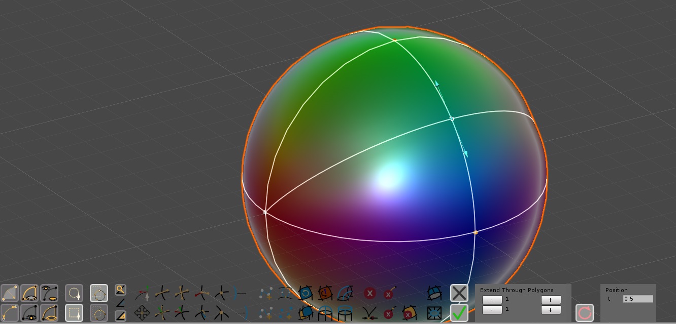
Fig. 19 Subdivide Edge Operation applied to curved triangular polygons.
You can cut a model as many times as you want. An important limit to keep in mind is that the tool actually cut polygons sides, not edges. So: if a polygon side has only one edge, everything will go as explained. If you try to cut a single edge being part of a side of a polygons using more edges, the software will still cut the side and not the edge (so you can't cut further an edge with this tool if you do not extend the cut through polygons each time). If you want a polygon to have a side with more than two edges, you need to do that manually following the steps in (C.2)
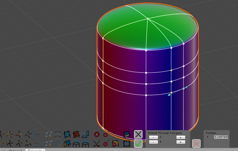
Fig. 20 Subdivide Edge Operation applied more times. Here we used a Cylinder as starting primitive.
(C.2)Manually Subdivide Edges or Polygons
You can of course subdivide edges and polygons manually. This will take some time, but not too much when you know what to do. A subdivision process basically should follow this two steps:
- Delete parts you want to subdivide. You should do this using planning your selections carefully. This is also a good time to use Cancel Polygons or Cancel Edges rather than the most general Cancel Edges.
- Regenerate the Edges you wanted to subdivide with Put Edges. Once you learn to use Put Edges, it's pretty fast to regenerate removed edges. Here you can rebuild edges you canceled using a greater number of edges for instance.
- Make Polygons. After you have finished rebuilding the structure of your model, rebuild everything by selecting the new Edges (actually you need to select vertices, not edges: you can do this with Extend To Vertices if you think you miss something) and press Make Polygons.
- Reshape. In the end, you will need to correct the shape. The editing normals on
vertices and edges will be most likely bad; you can try to use
 Fix Normals to correct them. You may also experiment different edge normals setups using the Advanced Shape Tools.
Shape Control may also help to correct circular or rotational surfaces. For everything else, you will step back to Shape Tools to fix the elements.
Fix Normals to correct them. You may also experiment different edge normals setups using the Advanced Shape Tools.
Shape Control may also help to correct circular or rotational surfaces. For everything else, you will step back to Shape Tools to fix the elements.
(D.1)Duplicate a Part and Weld the two clones together with Remove Doubles
Here we will see how to use Duplicate and Remove
Doubles to increase the complexity of a model
About Duplicate
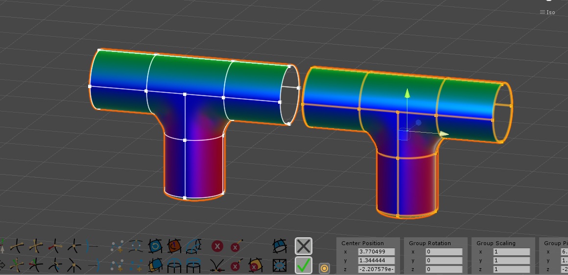
Fig. 21 A Duplicated Shape (it's a TShapeAlt1x) during Duplicate Operation.
Duplicate Operation allows you to duplicated a part of your model.
You need to select something first (even a single vertex, or the entire shape). Pressing the button will put you in an operation state like similar operations we have seen around, and you will need either to Close or Apply it to exit.
- After you press the button, a new clone of your selection will be generated and will become selected in place of the original selection.
- Before getting out of the operation, you can use Unity Transform Tools to move, rotate or scale the cloned elements.
- You are free to change your selection if you need, the tool will always affect the originally cloned elements.
Reflected Duplicates: there is no direct way (as
version 1.0 of the Maker) to Reflect a Duplicate. The most direct sequence is : in Duplicate
Operation (or also in Transform Operation) manually write -1 in the of field
of a scaling component, either x, y or z depending on the reflection result you want to accomplish. Then exit the Duplicate
Operation(or the Transform Operation). With the same polygons selected (correct
the selection if necessary), press on Flip Polygons. Finally:
press on Fix Normals to correct issues with normals.
Weld the Duplicates

Fig. 22 Welding two duplicated parts with Remove Doubles.
If you are duplicating a shape with an open part, you can than exploit Remove Doubles to Weld them together.
(D.2)Connecting two separated Parts with a Bridge Joint
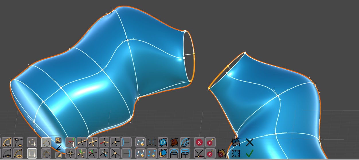
Fig. 23 Bridge Joints Correct Setup
When you have two open surface you can use Bridge
Joints to connect them. This action (together with Hole Joints and Extrude Path which are discussed in point (B.3))
is a preview of a paths systems which we are going to introduce in one of the next
versions of Curved Poly Maker. At the moment, it does its job well only if you make a good setup first: technically speaking, you need to have two closed set of edges and the edges must have all one polygon on a side and nothing on the other side; it may be better if you have put alignments first on that edges through the border. Basically, they have to be two closed borders for two open surfaces. All the edges should be curves (lines may work, but it's not guaranteed), all the vertices should be smooth (sharp vertices may work, but it's not guaranteed). For example, this is the case if you start with a Cylinder Border primitive, or if you have generated a tubular surface exploiting Make
a Circle as explained in (A.2). If this is your case, you need to select one of
the edges on each border before activating Bridge Joints (they must be only two edges, or the button will be disabled): since the edges are aligned, the software will automatically grow the selection through the border. Know that this operation may still try to do something in any case once you have at least two edges selected: if you don't like the result you can always Undo it.
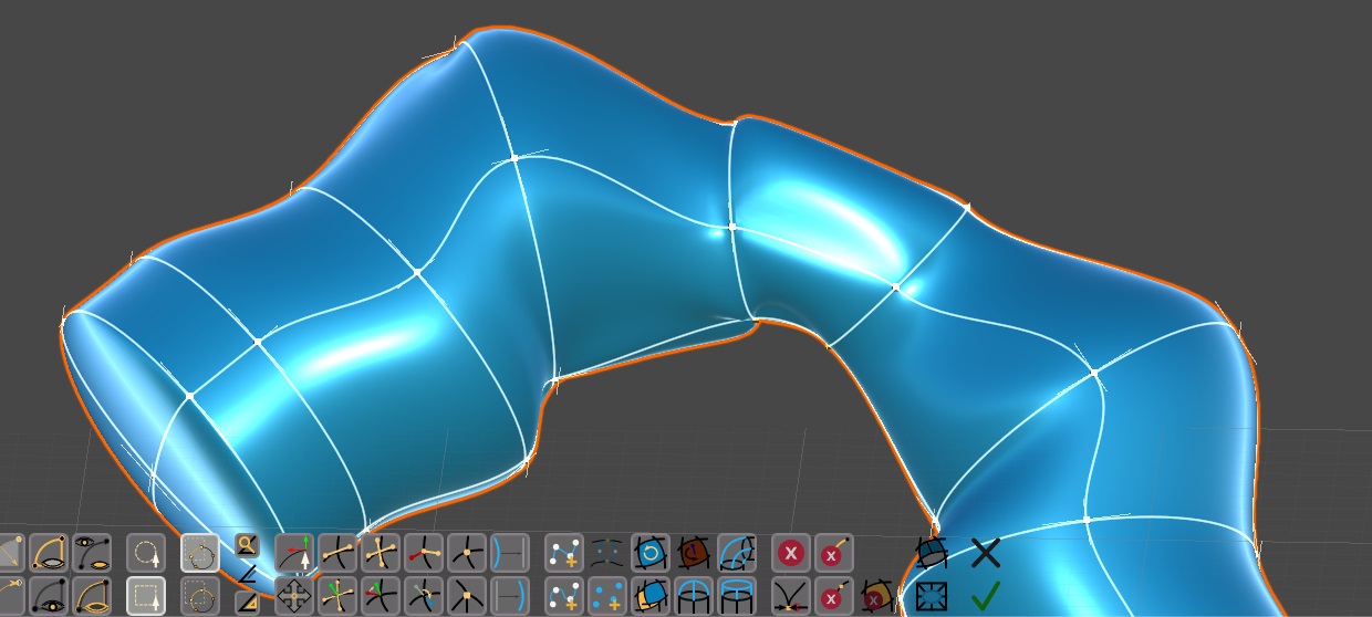
Fig. 24 After pressing the Bridge Joints button
(D.3)Manually Connect two Parts with Put Edges and Make Polygons
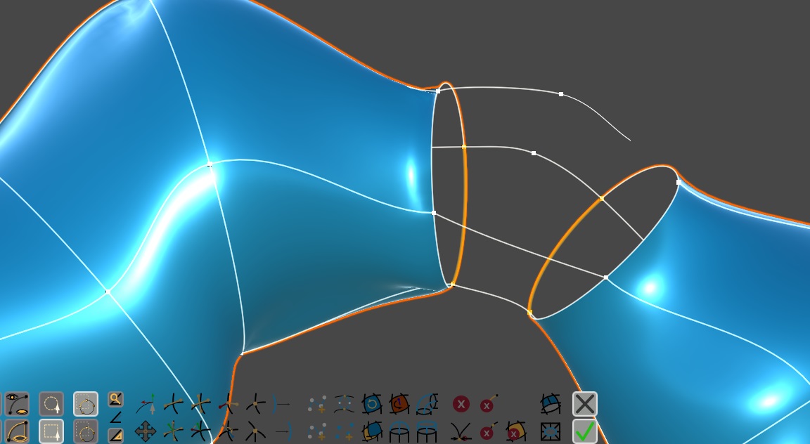
Fig. 25 Manually Connect Two Parts: here we are using Put Edges on the example of Bridge Joints to create a net of curves to connect the two parts.
You can always connect two open parts with Put Edges and Make Polygons.
(E)Import LOW POLY Meshes to transform into Curved Polys
You can use Composition Tools to insert a Mesh in your
model. This is performed with the  Insert Mesh button. You will have to choose a mesh in your project.
After the import a curved poly will be generated:
Insert Mesh button. You will have to choose a mesh in your project.
After the import a curved poly will be generated:
- All Made of Lines, so no Curved Edges
- All Made of Sharp Vertices, so without any kind of smoothness
- All Made of Triangles, directly imported by the triangles array in the mesh.
So, after the import, you should consider using:
- Cancel Edges to remove edge between two adjacent triangles, so
that you can create a quad soon afterwards with Make Polygons.
 Make Edges Curved to make all the linear edges curved
 Make Vertex Smooth to make all the vertices smooth
- Fix Normals: to force a recomputation of editing normals on edges
and vertices; this may be necessary after using Make Edges Curved or Make Vertex
Smooth.
- Flip Polygons: to flip polygons which look watching the wrong
side.
- Normalize Handles Direction: to correct handles on smooth vertices
which you think are not set up correctly.
 Auto Align Handles: to generate alignments through all the model
(there are many tools which are based on alignments, so this is always a good idea).
Auto Align Handles: to generate alignments through all the model
(there are many tools which are based on alignments, so this is always a good idea).
The process of converting a mesh into a Curved Poly may become a complex stuff in some situations. Refer to the chapter About fixing stuff for some more deep instructions.
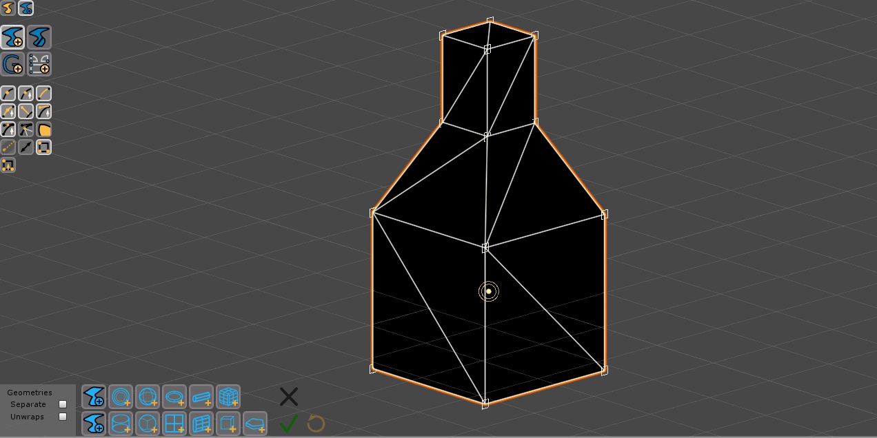
Fig. 26 An inserted mesh
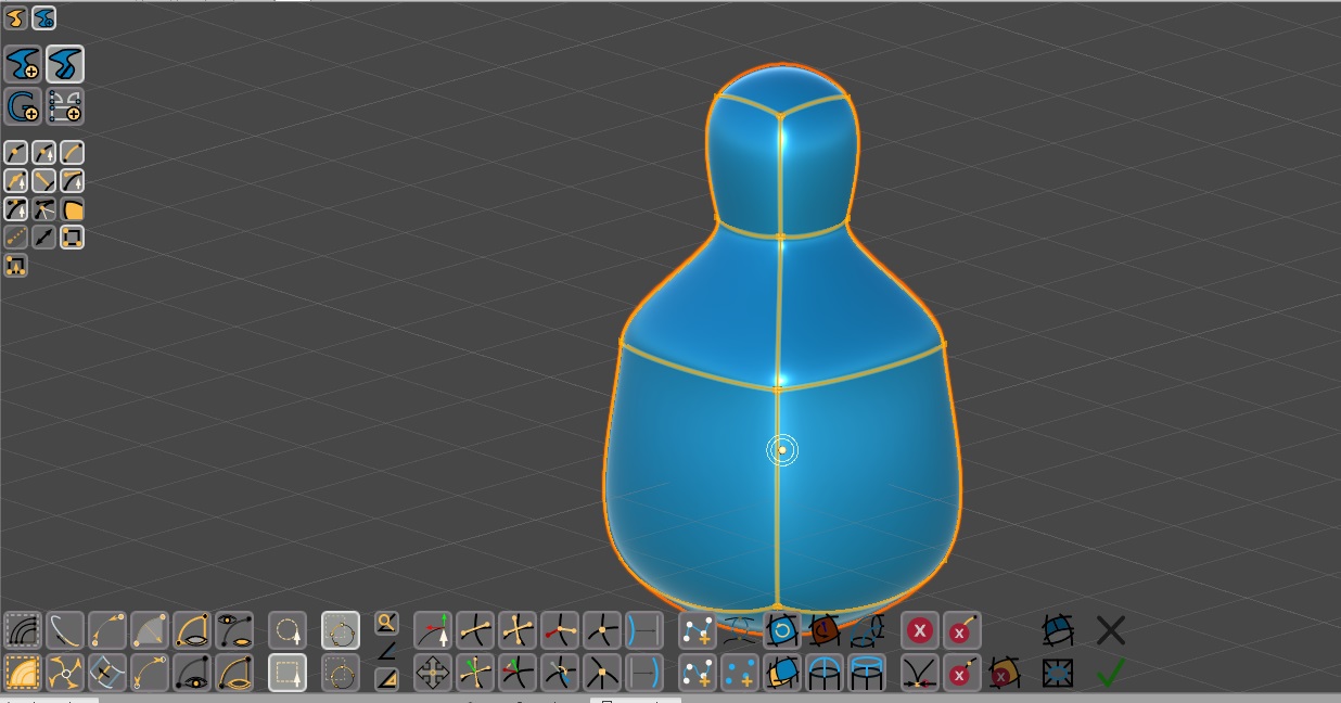
Fig. 27 The inserted mesh after some edges removal (we wanted quads here, not triangles), a Make Vertex Smooth, a Make Edges Curved and a final Make Polygons.
<< Prev Next >>